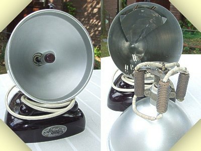
Original Hanau Alpinette PL36 sunlamp
SERIAL-BALLAST
To limit the current I through a discharge tube, a
ballast with a resistance R had to be connected in
series with the discharge tube T and the voltage
source U. The value of R had to be constant or, even
better, had to increase with increasing current.
According Ohm's law, the current through the circuit
was limited to its short-circuit current I = U/R. The
power to be dissipated in the resistor equalled U x I,
the product of the supply voltage and the current. At a
supply voltage of 230 volts and a desired working
voltage over the discharge tube of for instance 55
volts at a working current of 1,4 Ampere, a serial
resistor of (230-55) V/ 1,4 A = 125 Ohm would be
needed. Its power dissipation then would be (230-55)
V x 1,4 A = 245 Watt. The discharge
tube under this circumstances would
dissipate 55 V x 1,4 A = 77 W so with
this kind of limitation about three quarters
of the applied power was dissipated in a
resistor whose only purpose was to limit
the current through the discharge tube. A
good example of such a configuration is
the Original Hanau Alpinette PL36
sunlamp on display here. The resistor
right of the discharge tube was
responsible for the ignition of the lamp, as
will be explained in the next section of
this building.